Episode 11 · Antennas and filters · Series 01: The Listening Station
What is on the roof, and what did I get wrong?
 Coming soon
- Release
- Length
- 3:29
- On the dial
- The roof
- Signal
- FM broadcast
What it covers
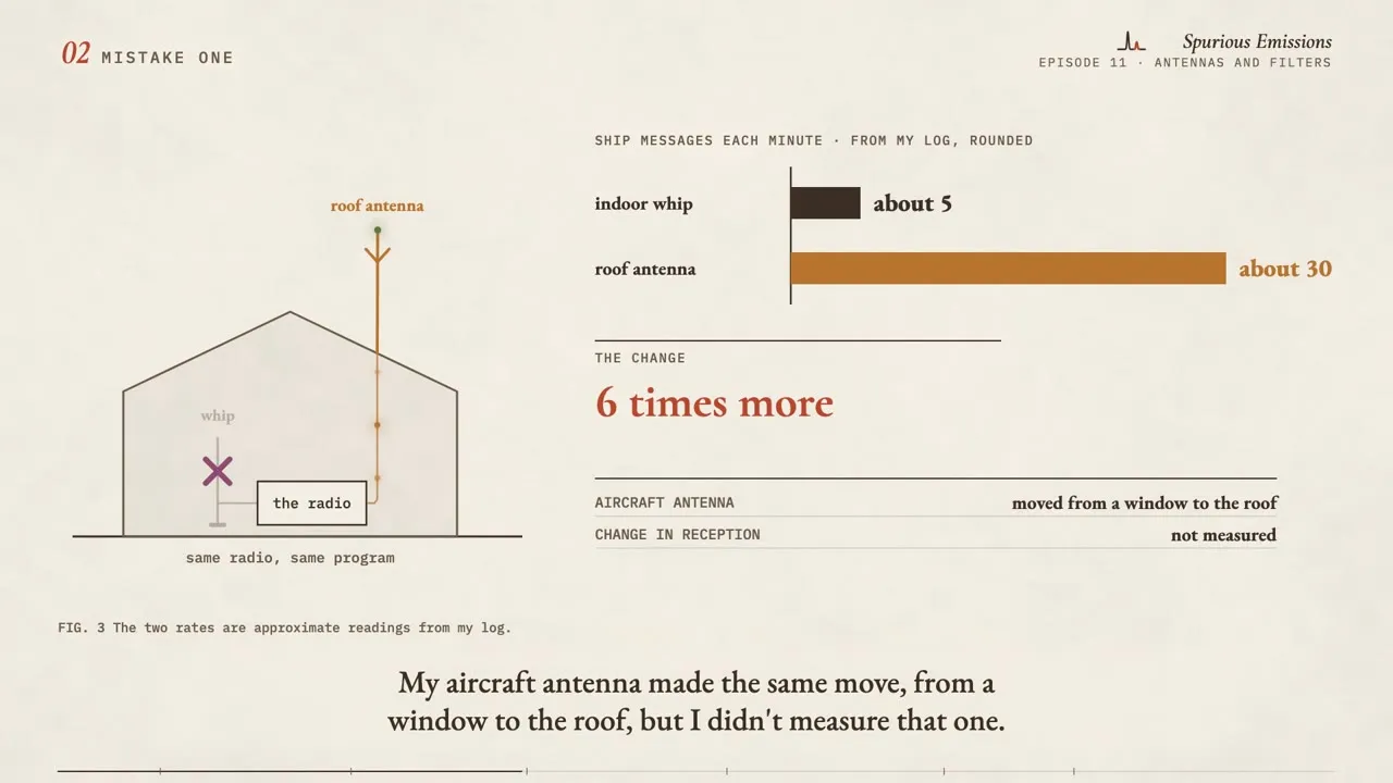
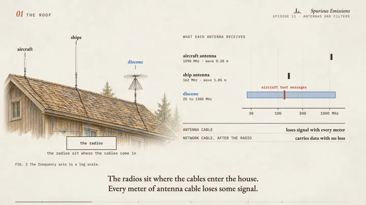
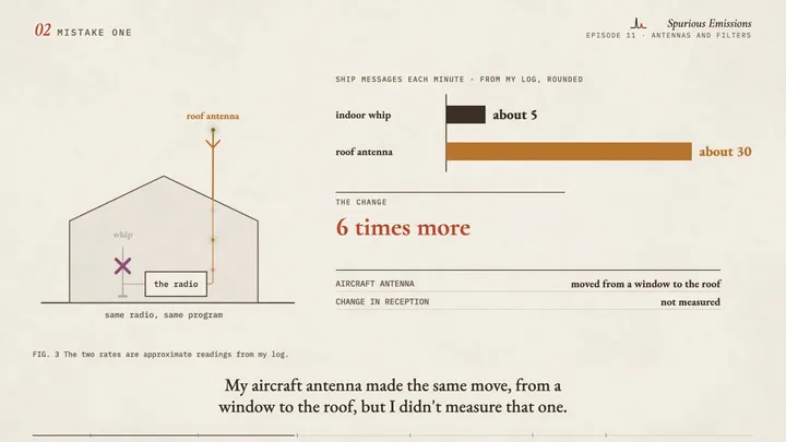
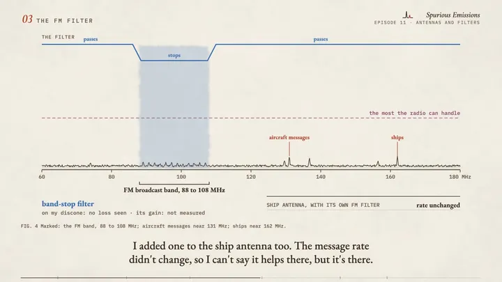
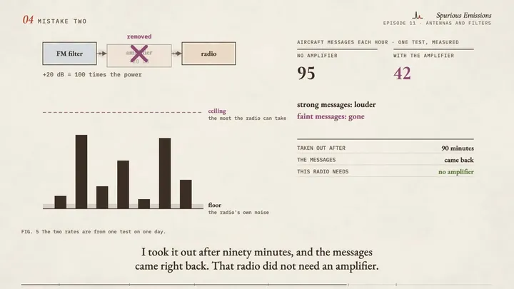
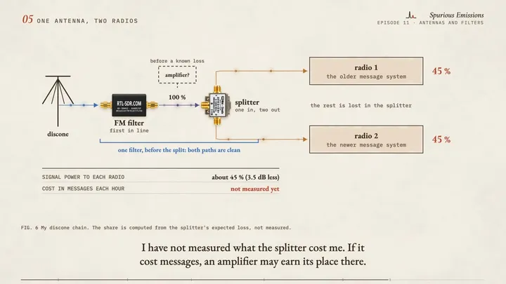
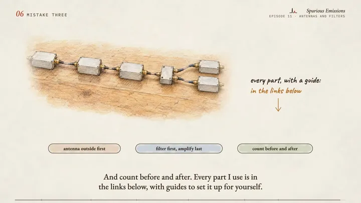
My listening station has four antennas, and I made a mistake with most of them. In this video I show what each antenna is for, what a band-stop filter, a splitter and a limiter do, and three things I got wrong: an antenna indoors, an amplifier that halved my message rate, and a shortwave loop that still sits next to a computer.
Chapters
- 0:00Intro
- 0:18The roof
- 0:49Mistake one
- 1:18The FM filter
- 1:51Mistake two
- 2:27One antenna, two radios
- 2:48Mistake three
Frames from the draft

Gear in this episode
| Diamond D-130J discone antenna | the wide-band antenna on my roof (25 to 1300 MHz) |
| FlightAware 1090 MHz fiberglass antenna | the antenna on my roof for aircraft |
| AIS-band vertical antenna | the antenna on my roof for ships |
| MLA-30+ loop antenna | the small active loop antenna for shortwave |
| RTL-SDR Blog FM band-stop filter | the filter that blocks FM broadcast stations on my wide antenna |
| Nooelec Flamingo FM | the filter that blocks FM broadcast stations |
| Mini-Circuits ZX10-2-12-S+ splitter | feeds two radios from one antenna (mine came from a surplus dealer) |
| TAPR RF Limiter | protects the receiver input from strong signals |
| RX-888 Mk II | the receiver that hears all of shortwave at once (mine is from OpenSourceSDRLab) |
| Turn Island Systems F3060 filter | the 30 MHz low-pass filter in front of my shortwave receiver |
| CyberPower CP1500PFCLCD UPS (1500 VA, sine wave) | the battery backup that keeps almost all of my station running through a power cut |
Software and references
| Discone antennaen.wikipedia.org | how the wide-band antenna works (Wikipedia) |
| Band-stop filteren.wikipedia.org | the kind of filter that removes one band and passes the rest (Wikipedia) |
| Dynamic rangeen.wikipedia.org | the room between a radio's noise floor and its ceiling (Wikipedia) |
| Loop antennaen.wikipedia.org | small receiving loops for shortwave (Wikipedia) |
What is simplified, and what is invented
- The amplifier that made reception worse is a generic part with no known model, so it has no link.
- The house is a generic drawing. It shows no real layout, and the antennas are not to scale.
- The spectrum in the FM filter chapter is an invented illustration, not a measurement. Only the band edges and the two marked frequencies are real.
- The floor and ceiling drawing in the amplifier chapter is an illustration of the idea. The bar heights are invented. The explanation is my best reading of the test, not a measurement.
- The amplifier numbers come from one test on one day, made before the splitter was installed.
- The ship message rates are approximate readings from my log, rounded.
- The share of signal after the splitter is computed from the expected loss of the part, not measured.
- The loop sketch is not to scale and shows no real layout.